

Product overview
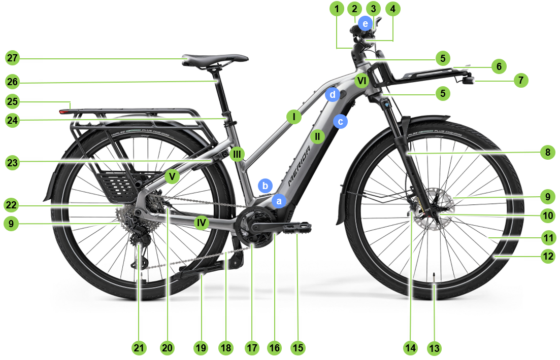
| Item | Feature |
|---|---|
| a | Motor |
| b | Rechargeable battery / battery cover |
| c | Display and control unit |
| d | Battery lock |
| e | Display and control unit |
| Item | Feature |
|---|---|
| 1 | Stem |
| 2 | Handlebars |
| 3 | Brake lever |
| 4 | Shifter |
| 5 | Headset |
| 6 | Front luggage carrier |
| 7 | Front headlight |
| 8 | Suspension fork |
| 9 | Brake disc |
| 10 | Hub |
| 11 | Spoke |
| 12 | Rim |
| 13 | Valve |
| 14 | Front brake |
| 15 | Pedal |
| 16 | Crank |
| 17 | Chainring |
| 18 | Chain |
| 19 | Double kickstand |
| 20 | Rear brake |
| 21 | Rear derailleur |
| 22 | Cassette |
| 23 | Padlock |
| 24 | Seatpost clamp |
| 25 | Carrier |
| 26 | Seatpost |
| 27 | Saddle |
| Item | Feature |
|---|---|
| I | Top tube |
| II | Down tube |
| III | Seat tube |
| IV | Chain stay |
| V | Seat stays |
| VI | Head tube |
General information
About this manual
This user manual provides important information and instructions on handling MERIDA bicycles to ensure safe and proper use of the bicycle. It is intended to provide you with a comprehensive presentation and description so that you can use your bike safely in accordance with its intended use.
In order to use your bike safely, you must observe all safety information and instructions in this user manual.
| Notice | |
|---|---|
Symbols
Different text attributes, spellings and text structures make this document easier to read.
The text attributes (highlighting) within the document have the following meaning:
| Character | Meaning |
|---|---|
| ► | Instruction |
| • | List item |
| 1. | Instructions for action |
Terms and abbreviations
The following terms and abbreviations are used in this user manual:
| Initials | Meaning |
|---|---|
| CC | Cross-Country |
| TK | Trekking |
| HD | Heavy-Duty |
| SL | Super-Light |
| FR | FreeRide |
Safety instructions
Safety and warning notices warn of hazards and their consequences when handling the bicycle and provide instructions to ensure the safe use of the bicycle. In addition, safety instructions specify actions to avoid the hazard.
The warnings in these original operating instructions are structured as follows:
Symbol and signal word
| Notice | |
|---|---|
| DANGER | |
|---|---|
| Warning | |
|---|---|
| CAUTION | |
|---|---|
| Notice | |
|---|---|
Warranty terms
| Notice | |
|---|---|
Your MERIDA eFLOAT HD has been carefully manufactured and will normally be delivered to you fully assembled and ready to ride by your MERIDA dealer.
During the first two years after purchase, you are fully entitled to the statutory warranty on new purchases within the EU. If your eFLOAT HD has any defects, your MERIDA dealer is the right contact for you. Keep the proof of purchase for such a case.
To ensure the warranty, a long service life and durability of your MERIDA eFLOAT HD, you must use your eFLOAT HD only for its intended purpose and observe the following points:
Permitted total weight
The maximum weight is the sum of the rider, the eFLOAT HD, equipment, luggage, attachments and accessories.
- Torques of the screws
- Prescribed maintenance intervals
- Use only original spare parts and accessories
- Maintenance of the suspension at least once a year by your MERIDA dealer
- Instructions for BOSCH rechargeable battery (only e-bikes / Bosch)
Notes on wear
| CAUTION | |
|---|---|
Some components of your MERIDA eFLOAT HD are subject to functional wear and must be replaced or serviced regularly when they reach their wear limit:
rechargeable battery, chain, brake pads, brake fluid, brake discs, brake lines, seals of suspension elements, bearings of the rear triangle, hubs and headset, paintwork and decals, grips, chainrings, chainstay protectors, tyres and tubes, sprockets, saddle cover, derailleur pulleys, lubricants.
Warranty on your MERIDA eFLOAT HD
The following manufacturer’s warranty, which goes beyond the statutory warranty, applies from the date of sale to the original purchaser:
- Lifetime guarantee in the event of frame breakage for all frames
- 5 years on rigid forks
- 2 years for commercial use: Warranty for frames and rigid forks
- 2 years on all MERIDA components
- Statutory warranty for paintwork and undercoated decals
In the event of a warranty claim, MERIDA reserves the right to supply the respective successor model in the available colour - in the event of non-availability, the respective higher-quality model.
The warranty for shock absorbers, suspension forks and other branded accessories is not handled by MERIDA, but by the national distributors of the parts manufacturers.
Manufacturer’s warranty
The manufacturer’s warranty is only valid for the original purchaser on presentation of the customer’s proof of purchase, which must show the date of purchase, address of the dealer, model and frame number.
The warranty does not include labour and transport costs or consequential costs caused by defects.
Competition use is permitted within the scope of the respective utilisation category.
Excluded is damage caused by:
- Wear and tear
- Lack of care and maintenance
- Falls/accidents
- Overloading due to excessive load
- Improper assembly and handling
- Attachments and conversions of additional components
In the interests of a long service life and durability of the components, the manufacturer’s installation instructions, the prescribed maintenance intervals and regular replacement of safety-relevant components must be observed.
Safety
Intended use
Pedelec
A pedelec combines the characteristics of a conventional bicycle and an electric drive. The pedalling is supported by an electric motor.
Each type of pedelec is built for a specific purpose. These purposes are divided into categories according to the DIN EN 17406 utility classification of bicycles. Only use your MERIDA pedelec for its intended purpose; otherwise, there is a risk that your pedelec will not be able to withstand the loads. This can lead to unforeseeable accidents.
Pedelecs (power electric cycles) are bicycles on which the auxiliary motor only switches on when the rider pedals. If pedalling stops, the motor assistance also switches off.
When setting off uphill or if the pedelec is being pushed, the starting or pushing aid provides assistance up to a speed of 6 km/h, even if you are not pedalling.
The sound pressure level (A-weighted) at the rider’s ear is below 70 dB(A).
The legal regulations for riding your MERIDA pedelec:
| Pedal assistance | up to max. 25 km/h |
| Helmet compulsory | recommended |
| Driving licence or moped test certificate | No |
| Type approval or EU type approval | No |
| Insurance licence sticker | No |
| Use of cycle paths | mandatory in and out of town |
| Vehicle class | bicycle |
| Age limit | No |
| Child seat | permitted if the permissible total weight is adhered to and the seat is installed correctly and safely |
| Child trailer | permitted |
| Sound pressure level at the rider’s ear | below 70 dB(A) |
Permitted total weight
The permissible total weight of your pedelec is made up of the following (all figures in kg):
- weight of the pedelec
- weight of the luggage
- total weight of the trailer including load and/or persons
The weight of your MERIDA pedelec is stated on the type plate. If this is not the case, the weight of your pedelec is less than 25 kg. To calculate the total weight in this case, assume a weight of 25 kg.
| Warning | |
|---|---|
Category 2 CROSS
MERIDA Category 2 CROSS pedelecs are intended for use on paved terrain, i.e. on paved roads and cycle tracks or on country tracks with finely gravelled, sandy or earthy surfaces with moderate ascents and descents. Under these conditions, there may be contact with uneven terrain and repeated loss of tyre contact with the ground. Rolling off an edge/step and jump heights are permitted for a short time up to a maximum height of 15 centimetres.
The intended purpose is leisure and trekking requiring moderate effort.
Typical speed range: 15 km/h to 25 km/h
MERIDA pedelecs in Category 2 come with a lifetime guarantee.
Maximum total weight: 150 kg
Improper use
Use outside the category assigned to the bicycle in accordance with the DIN EN 17406 classification of bicycles is considered improper use.
In addition, the following are considered improper use:
- the replacement, use and installation of unauthorised components
- the fitting of a combustion engine or electric motor
- any repair work on carbon parts
- mechanical modification of existing parts (grinding, filing, drilling etc.)
- removal of safety equipment (e.g. reflectors) or holders
- increasing the performance (tuning)
| Warning | |
|---|---|
Trailer operation
Your MERIDA eFLOAT HD is approved for use with trailers for transporting loads and children weighing up to 27 kg.
Up to two children can be accommodated in special child trailers that are towed behind the bike.
Please note when using a trailer:
- The trailer is considered to be part of the total authorised weight with its actual weight, including the load.
- The trailer coupling may only be attached to the rear axle or on special mounts on the dropout.
- It is not permitted to attach the trailer coupling to frame tubes, rear stays or the seatpost.
- If it is necessary to replace the original thru axle in order to attach the trailer coupling or to clamp an adapter to the original thru axle, ensure that the axle thread and the thread of the axle nut completely overlap.
- Replacement axles must comply with the Technical Specifications of the original MERIDA axle (clamping width, thread pitch and thread length, material and diameter).
- If lighting equipment is concealed by the trailer, it must be visibly attached to the trailer. If riding at night, attach a battery/rechargeable battery light to the rear of the trailer.
- The maximum permissible speed specified by the trailer manufacturer must be observed. Follow the trailer manufacturer’s instructions.
- Only transport persons in authorised trailers.
| Warning | |
|---|---|
Guide to component replacement for CE-labelled e-bikes / pedelecs
Guide to component replacement with pedal assistance up to 25 km/h
| Category | Description |
|---|---|
| Category 1 | Components that may only be replaced after approval by MERIDA / e-system provider. |
| |
| Category 2 | Components that may only be replaced after approval by MERIDA. |
| |
| Category 3 | Components that may only be replaced after approval by MERIDA or the component manufacturer system supplier. |
| |
| Category 4 | Components for which no special approval is required. |
| |
| Category 5 | Special instructions for attaching accessories. |
|
* Note on category 3: The component manufacturer can only give approval if the component has been adequately tested in advance in accordance with its intended use and the relevant standards and a risk analysis has been carried out.
Transport and storage
Transport
Your MERIDA eFLOAT HD has been carefully manufactured and will normally be delivered to you fully assembled and ready to ride by your MERIDA dealer.
| Notice | |
|---|---|
Transport of MERIDA bicycles by vehicle
Your MERIDA eFLOAT HD can be transported on or in a vehicle.
- Always ensure that the eFLOAT HD is securely attached to the vehicle, inside or outside, and check the attachment regularly.
- Remove all objects and detachable accessories from the luggage rack.
- If applicable, remove the child seat.
Observe the transport conditions of the manufacturer of your bike rack.
Before transporting several bikes on one bike rack, find out what the total load capacity of the bike rack is authorised for and how high the roof load or drawbar load of the tow bar is.
Make sure that all moving and loose parts and the control unit are removed and stowed safely in the vehicle for the journey.
Country differences in the labelling of bicycle transport:
Find out about the regulations for transporting bicycles in the countries you are visiting.
Transport of e-bike rechargeable batteries
Remove the rechargeable battery and battery cover of your MERIDA eFLOAT HD before transporting it and store it securely in the vehicle.
Storage
Short time
If you maintain your MERIDA eFLOAT HD regularly during the season, you don’t need to take any special measures.
Store your eFLOAT HD in a dry, well-ventilated place.
Longer time
The tubes gradually lose air during longer periods of inactivity. If the eFLOAT HD is left on flat tyres for a longer period of time, its structure may be damaged. Therefore, hang up the wheels or the entire eFLOAT HD or check the tyre pressure regularly.
Clean your eFLOAT HD and protect it against corrosion. You can obtain special care products for this from your MERIDA dealer.
Remove the rechargeable battery from your eFLOAT HD. Ideally, the rechargeable battery should be stored with a charge level of 30% and at temperatures between 0°C and 20°C in a dry environment. A well-ventilated room with a smoke detector, away from sources of heat or easily flammable materials, is best suited for storage.
Before the first ride
If you collect your e-bike from an authorised specialist dealer, your e-bike will already be in a ready-to-ride condition to ensure safe operation. Your dealer has already carried out a final inspection and a test ride.
Checking screws for tightness
To ensure the operational safety of your MERIDA eFLOAT HD, the component bolts must be tightened carefully. This should be checked both before the first ride and at regular intervals.
Use a torque spanner with which the correct screw torque can be set. Approach the prescribed maximum screw torque from below in half Newton metres and check the tight fit of the component again and again in between. Do not exceed the maximum screw torque specified by the manufacturer.
For parts for which no information is available, start with 2 Nm.
Get to know the e-system
You can find all information about your e-system at: (www.bosch-ebike.com)
The Purion 200 control unit is intended for controlling your e-bike and optionally for controlling an additional smart system generation on-board computer.
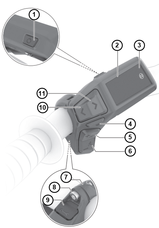
| Item | Control element |
| 1 | On/Off button |
| 2 | Display |
| 3 | Ambient light sensor |
| 4 | Selection button |
| 5 | Button to increase assistance level + / Bicycle lighting |
| 6 | Button to reduce assistance level - / Pushing aid |
| 7 | Bracket |
| 8 | Fastening screw |
| 9 | Diagnostic connection (for maintenance purposes only) |
| 10 | Scroll left |
| 11 | Scroll right |
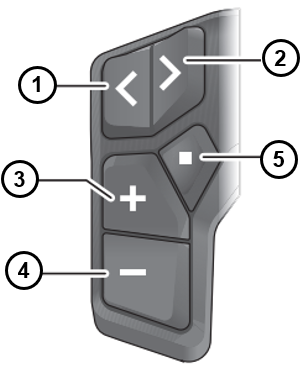
| Item | Control element |
| 1 | Scroll left |
| 2 | Scroll right |
| 3 | Increase assistance level / scroll up |
| 4 | Reduce support level / scroll down |
| 5 | Short press: Selection button / Open settings menu on the status screen / Acknowledge error codes Press and hold (>1 s): Open quick menu (from any screen except status screen) |
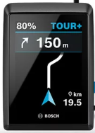
The Kiox 500 on-board computer is designed to display riding data on your smart system generation e-bike. A compatible smartphone with the eBike Flow app is required to use the Kiox 300/Kiox 500 on-board computer to its full extent.
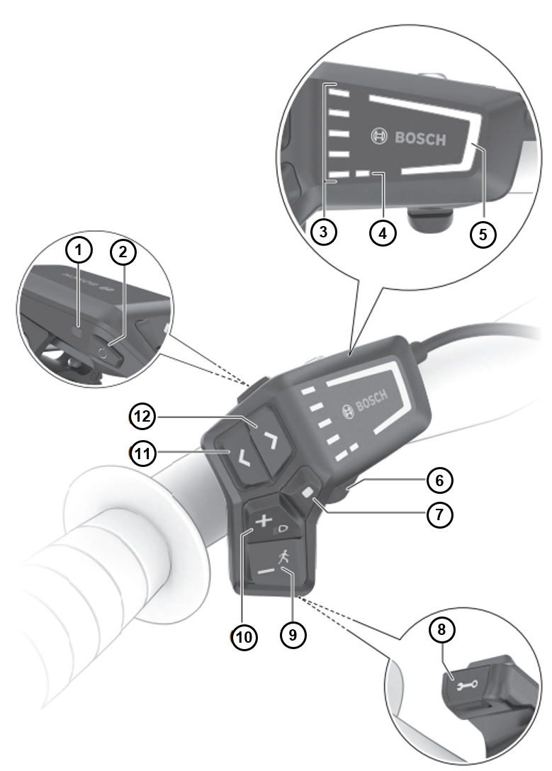
| Item | Control element |
| 1 | Ambient light sensor |
| 2 | On/Off button |
| 3 | Charge status display for e-bike rechargeable battery |
| 4 | ABS LED (optional) |
| 5 | Riding mode LED |
| 6 | Bracket |
| 7 | Selection button |
| 8 | Diagnostic connection (for maintenance purposes only) |
| 9 | Button to reduce assistance level - / Pushing aid |
| 10 | Button to increase assistance level + / bicycle lights |
| 11 | Button to reduce brightness / scroll backwards |
| 12 | Button to increase brightness / scroll forwards |
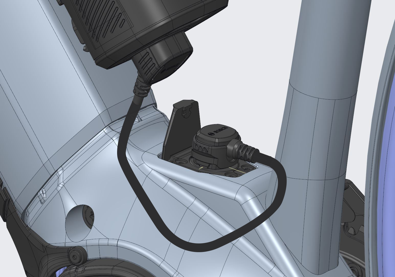
Connecting the charging cable
- Fold open the charging socket on the down tube.
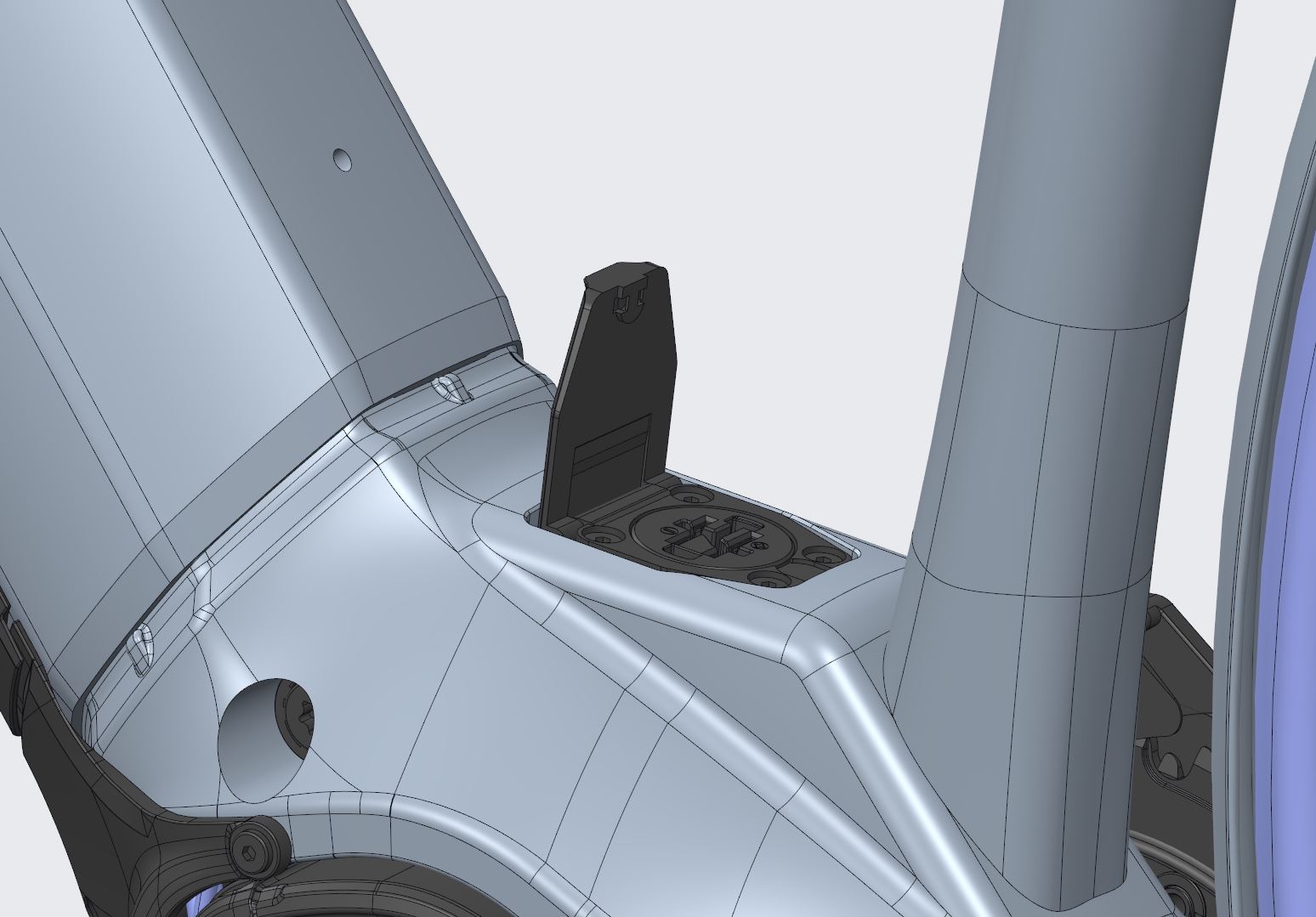
- Push the charging socket gently downwards until it engages.
- Insert the charging cable with the indentation on the left-hand side. The plug only fits in one position.
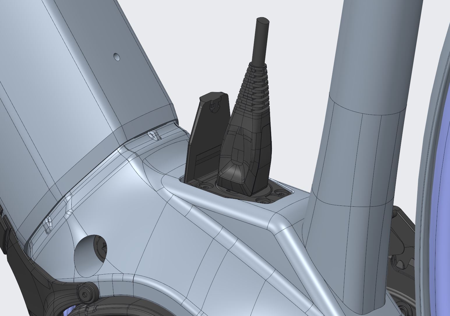
- Once charging is complete, remove the charging cable.
- Fold away the charging cable. It is secured with magnets.
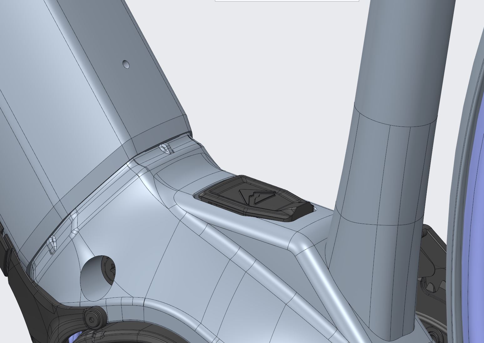
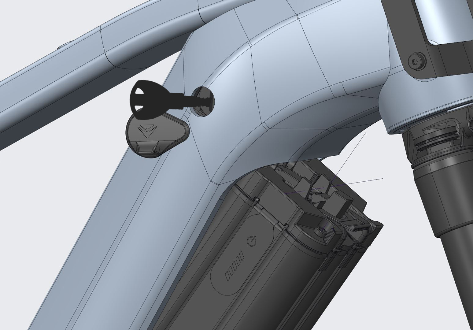
Learning how to remove the rechargeable battery
Procedure
- Turn the lever on the down tube clockwise to the vertical position to open the battery cover flap.
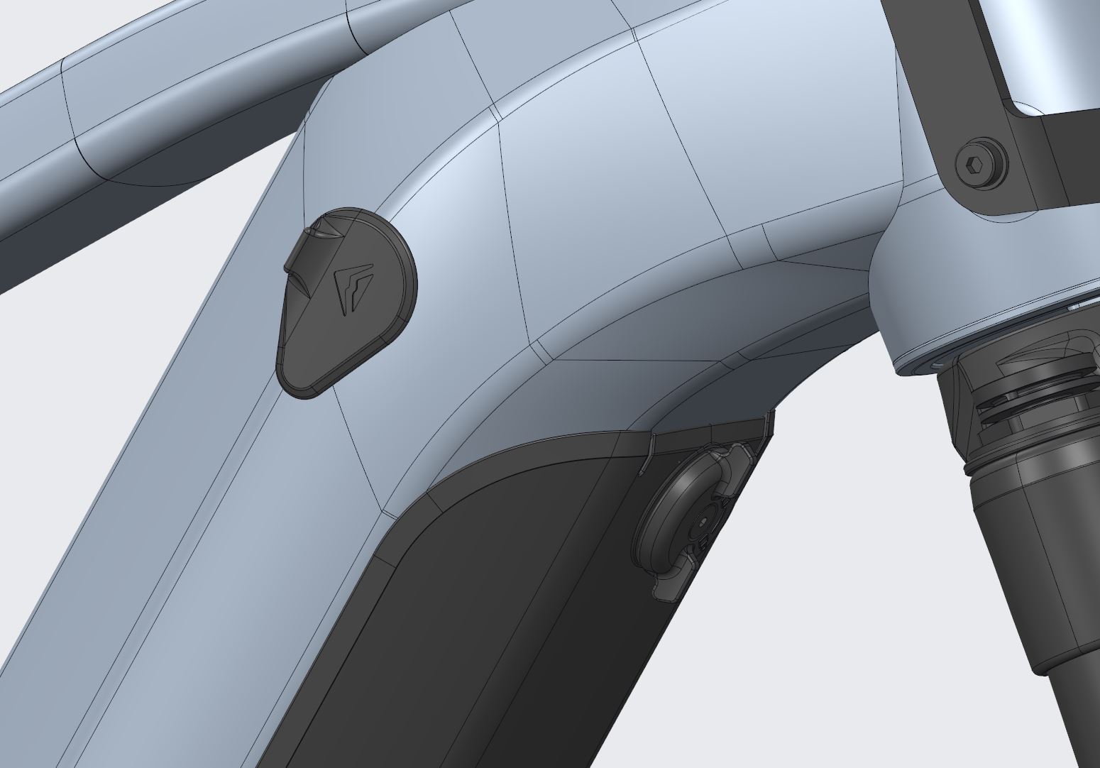
- Remove the battery cover.
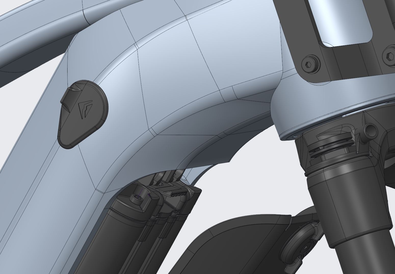
- Turn the key clockwise in the lock. The battery falls into the safety position.
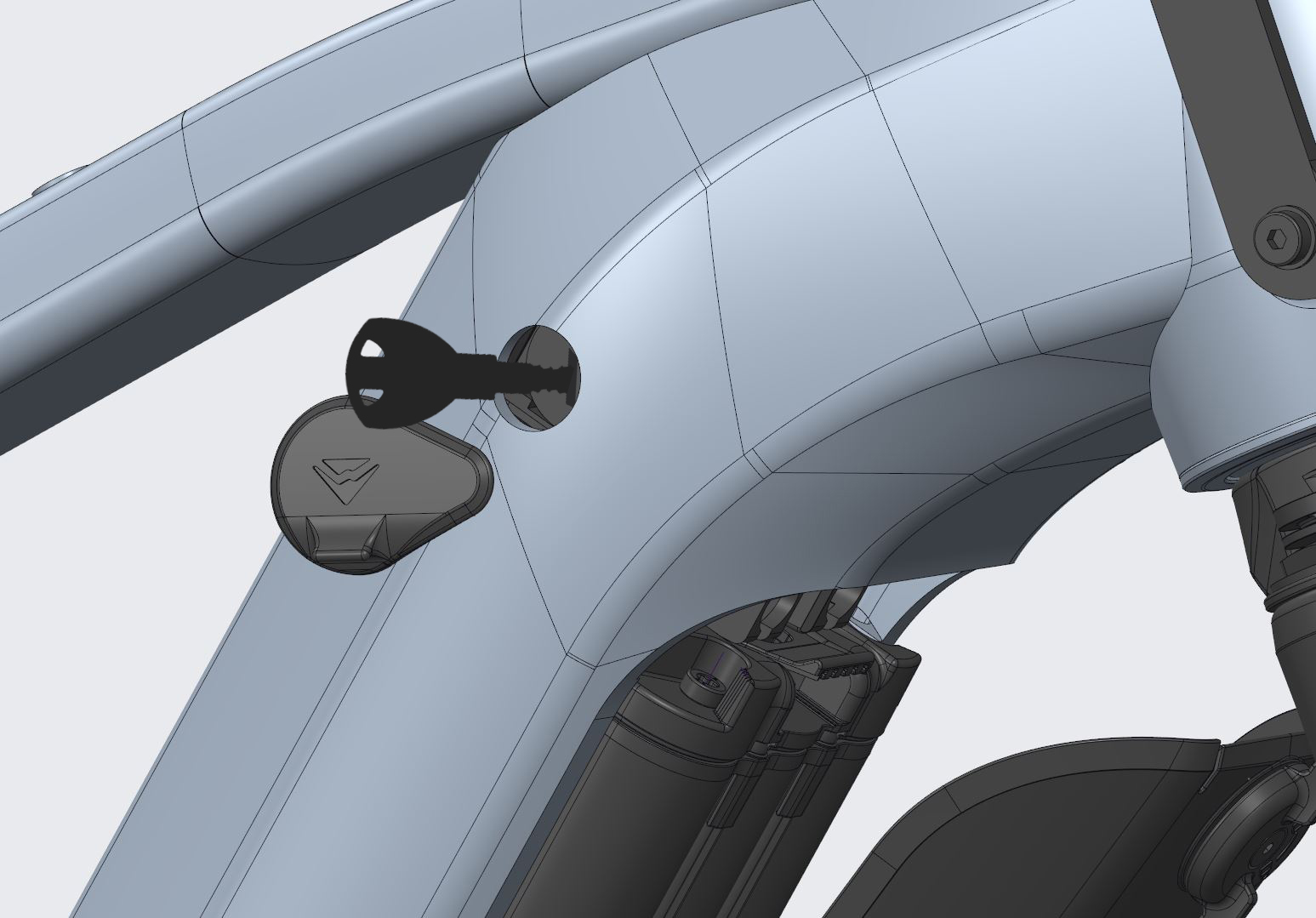
- Reach around the battery with one hand.
- With the other hand, activate the safety lever on the upper battery holder.
- Carefully remove the battery downwards.
Adjusting the saddle height
On a bike with a standard straight top tube, there should be at least 25 mm between you and the top tube when you are standing over the bike.
Determining the saddle height
To ensure that the correct saddle height is set:
- Sit on the saddle.
- Make sure that the lowerable seatpost is in the extended position.
- Place your right heel on the lower pedal.
- Your right leg should be slightly bent.
- If the leg is bent too much, push the seatpost upwards.
- If you can’t reach the pedal, push the seatpost downwards.
Checking the lowering function
- Operate the lever of the lowerable seatpost to ensure that it can be lowered and extended again without any problems.
- Test lowering the saddle for descents and technical passages so that you can ride comfortably in the lowered position.
Customisation according to personal riding style
The optimum height for flat and steep descents depends on your height and riding style. Adjust the saddle height if necessary to ensure comfort and control
Adjusting the seatpost
| Warning | |
|---|---|
To adjust the seat height to suit you, loosen either the quick release or the seatpost clamp at the top of the seat tube.
Loosening the seatpost clamp
- Use a suitable tool, e.g. an Allen key, to turn the clamping screw two to three turns anti-clockwise.
- Adjust the seatpost to the correct height and retighten the clamping screw.
- Do not pull the seatpost beyond the markings on the shaft (end, minimum, maximum, stop, limit etc.).
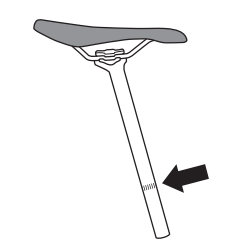
- Always grease the part of the aluminium support that is in the seat tube.
CAUTION
Clamping the seatpost
- Straighten the saddle again by aiming over the saddle tip towards the bottom bracket housing or along the top tube.
- Clamp the seatpost.
- Either tighten the quick release or tighten the seatpost clamp bolt to the torque specified on the clamp.
- Between each step, keep checking that the seatpost is firmly seated.
- To do this, hold the saddle firmly with your hands at the front and back and try to twist the saddle.
- If the saddle can be twisted, carefully tighten the seatpost clamping screw by half a turn and check the fit again.
Adjusting the handlebar height
The handlebar height relative to the saddle and the distance between the saddle and handlebars determine the inclination of the back. With low handlebars, you sit sportily and put a lot of weight on the front wheel.
The Ahead stem system is available, which can be used to vary the handlebar height
Stems for threadless Ahead® systems
On MERIDA bikes with Aheadset headsets, the stem is used to adjust the bearing preload. If the stem position is changed, the bearing play must be readjusted.
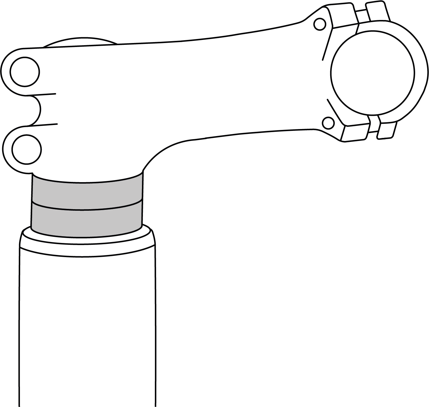
You can adjust the height to a limited extent by moving the spacers or flipping the stem on so-called flip-flop models.
Checking the tyre clearance and running
The diameter and width of the original wheels and tyres were selected to ensure sufficient clearance between the rotating wheel and tyre and the frame, fork and other components. Any modification to the wheels or tyres can affect this tyre clearance. Tyres that are marked as the same size may have different widths when they are fitted, inflated and installed on the bike. Always check the tyre clearance with the tyres fitted and fully inflated, even if the spare tyres are the same size as the tyres to be replaced.
The distance between a properly inflated tyre and any part of the bike should generally be at least 6 mm. Always maintain sufficient distance between the rotating rim and tyre and the frame, fork and other components. Check the frame and fork regularly for damage and the area around the wheel for any foreign bodies or objects.
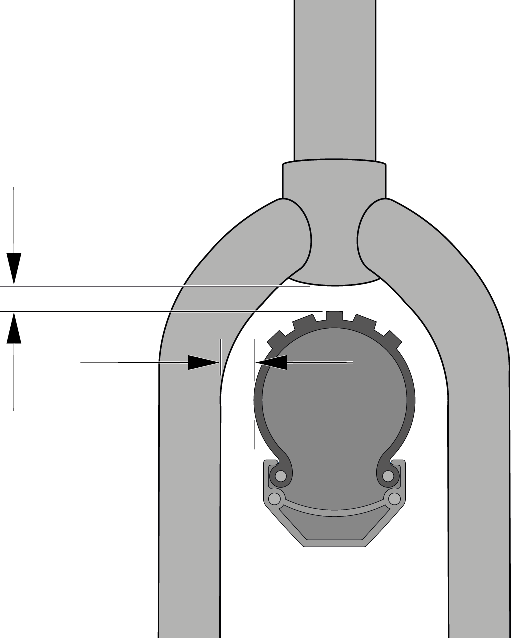
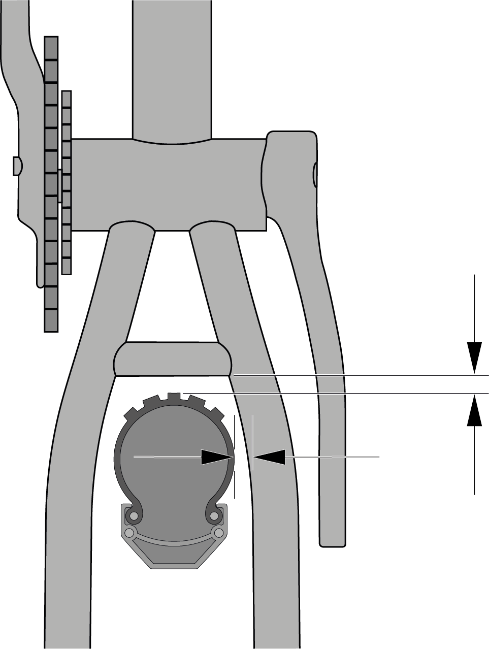
When riding the bicycle, the tyres must not touch the fork, frame or other components if a suspension element is fully compressed or the wheels are deformed by lateral forces. With a suspension fork, for example, the tyre must have a minimum distance to the fork crown even when the fork is fully compressed.
| Warning | |
|---|---|
Braking in the disc brake
New disc brakes must be braked in. Braking in helps to ensure constant and powerful braking performance as well as quiet braking under most riding conditions.
- To do this, get on the saddle and accelerate the bike to a moderate speed on a flat stretch of road.
- Then pull hard on the brake levers until walking speed is reached. Repeat this process twenty times.
- Accelerate to a higher speed and brake the bike to walking speed. Repeat this process ten times.
- Allow the brakes to cool down before continuing the ride.
- Contact your MERIDA dealer if the braking effect of your brakes decreases or the pressure point becomes spongy.
Checking the thru axle
Your bike is equipped with a thru axle to give the suspension fork and rear triangle the necessary stiffness.
| CAUTION | |
|---|---|
Removable axle lever
Our MERIDA TR rear axle lever can be used to tighten the rear axle, but when removed it also serves as a 6 mm and 4 mm Allen key, which can be used to tighten many other bolts on the bike.
To use the removable axle lever, pull out the lever on the non-drive side of the bike. To reinsert it, simply push it back into the centre of the thru axle.
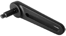
EAN: 4057094024029
Fitting the pedals
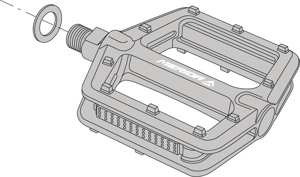
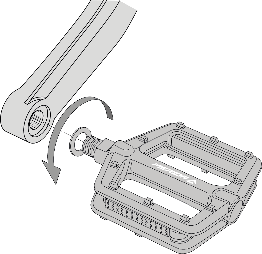
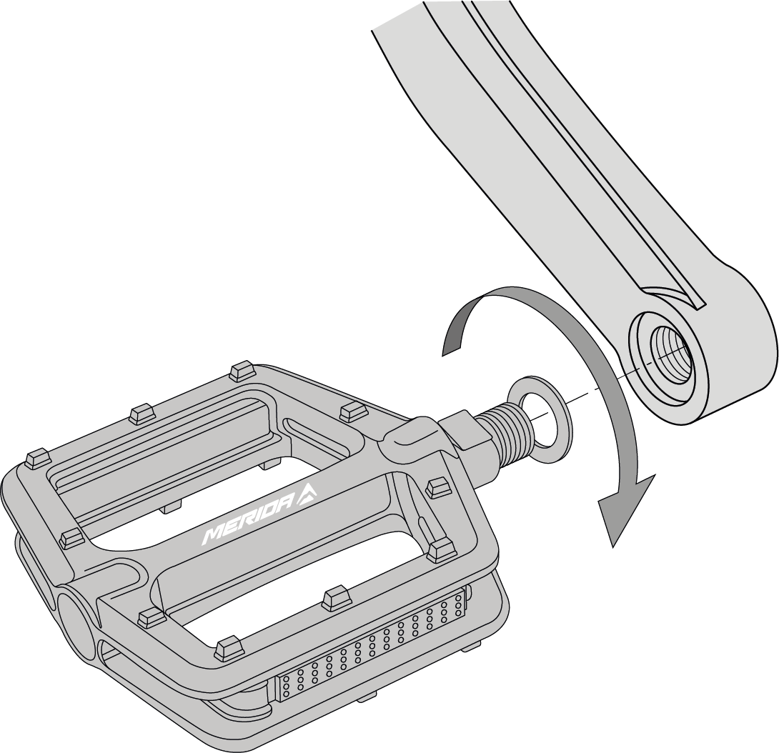
The pedals each have a right-hand or left-hand thread. The pedals are labelled with an “R” or “L” on the assembly side.
- Place the two washers included in the delivery contents on both pedal axles.Figure 10. Pedal with washer
- Turn the left pedal anti-clockwise into the thread in the left crank arm.
- Tighten the pedal with a tightening torque of 35 Nm.Figure 11. Left pedal
- Turn the right pedal clockwise into the thread in the right crank arm.
- Tighten the pedal to 35 Nm.Figure 12. Right pedal
Observing national regulations for road traffic Legal requirements
Legal requirements
If you want to ride your e-bike on public roads, it must be equipped in accordance with national regulations.
Germany:
In Germany, the necessary equipment for public road traffic is regulated in the “Road Traffic Licensing Regulations” (StVZO). Legally, our 25 km/h models have the same status as bicycles and are therefore subject to the same regulations. The following equipment must be fitted:
| Description | Special notes |
| White front light and white reflector | The front and rear lights and reflectors must be fitted during twilight hours, in the dark or when visibility conditions otherwise require it. The lights and reflectors must be firmly attached during operation, secured against unintentional adjustment under normal operating conditions and always ready for use. The front light must be adjusted so that other road users are not dazzled. Lights and reflectors must not be covered. |
| Red rear light and red reflector | |
| Pedal reflector | Both pedals must have front and rear yellow reflectors. |
| Spoke reflector | Two spoke reflectors each must be fitted to the front and rear wheels. Alternative: Tyres with reflective strips or spoke sticks on each spoke. |
Switzerland:
In Switzerland, the applicable regulations can be found in the ordinances on the technical requirements for road vehicles in Articles 213 to 218.
| Description | Special notes |
| White or bright yellow front light | The front and rear lights can be fixed or detachable. The front and rear lights must be switched on as soon as visibility conditions require and must be visible for 100 metres at night in good weather conditions. The front and rear lights must not dazzle other road users and must not flash. Lights and reflectors must not be covered. |
| Red rear light | |
| White reflector | At least one forward-facing and one rear-facing reflector with an illuminated area of at least 10 cm² must be permanently attached. The reflectors must be visible at night in good weather conditions at a distance of 100 metres in the light of a motor vehicle’s high beam. |
| Red reflector | |
| Pedal reflector | The pedals must have front and rear reflectors with an illuminated area of at least 5 cm². Racing pedals, safety pedals and the like are excluded. |
Austria:
To ride in public road traffic in Austria, you must comply with the 146th Ordinance / Bicycle Ordinance. These can be found in the Austrian Federal Law Gazette.
| Description | Special notes |
| White front light and white reflector | The front and rear lights and reflectors must be fitted during twilight hours, in the dark or when visibility conditions otherwise require it. The lights and reflectors must be firmly attached during operation, secured against unintentional adjustment under normal operating conditions and always ready for use. The front light must be adjusted so that other road users are not dazzled. Lights and reflectors must not be covered. |
| Red rear light and red reflector | |
| Pedal reflector | Both pedals must have front and rear yellow reflectors. |
| Spoke reflector | Two spoke reflectors each must be fitted to the front and rear wheels. Alternative: Tyres with reflective strips or spoke sticks on each spoke. |
| Notice | |
|---|---|
The pedelecs are limited to a rated continuous power of 250 W and a maximum speed of 25 km/h with electric pedal assistance, depending on the design. Only then do they have the same status as bicycles under road traffic law (§ 63a paragraph 2 of the StVZO).
Any increase in power and/or design speed beyond these limits results in the vehicle becoming a motor vehicle.
This has the following consequences
- Operating licence requirement
- Driving licence required (category depends on the maximum speed)
- Compulsory insurance and insurance sticker
- Helmet compulsory
- Use of cycle paths not permitted
- Provision of fatigue strength certificates for all safety-relevant components
| Warning | |
|---|---|
Inspection before every ride
Before you set off on your bike, give it a safety check - ideally on level ground and away from traffic.
Checking the parts for strength
- Check all screws for tightness, correct connection and correct fastening
- Check quick release, thru axles, screw connections on the front and rear wheel and other components
- Check the plug connections on the battery, control panel and display, as well as on the drive unit
- Check the battery in its holder and the locking mechanism
Bounce your bike from a low height onto the ground. Investigate any rattling noises that may occur. If necessary, check the bearings, screw connections and the correct seating of the battery.
| Notice | |
|---|---|
Checking brake efficiency
Carrying out a brake test:
- Test the brakes while at a standstill by pulling the brake levers towards the handlebars and applying the full braking force.
- Check that the front brake is working correctly. To do this, ride the bike at a slow speed and apply the front brake. The bike should stop immediately.
- Repeat this procedure for the rear brake as well.
The pressure point must be stable immediately. If you can only feel a stable pressure point after actuating the brake lever several times, you should have your bike checked immediately by your MERIDA dealer.
Checking the handlebars
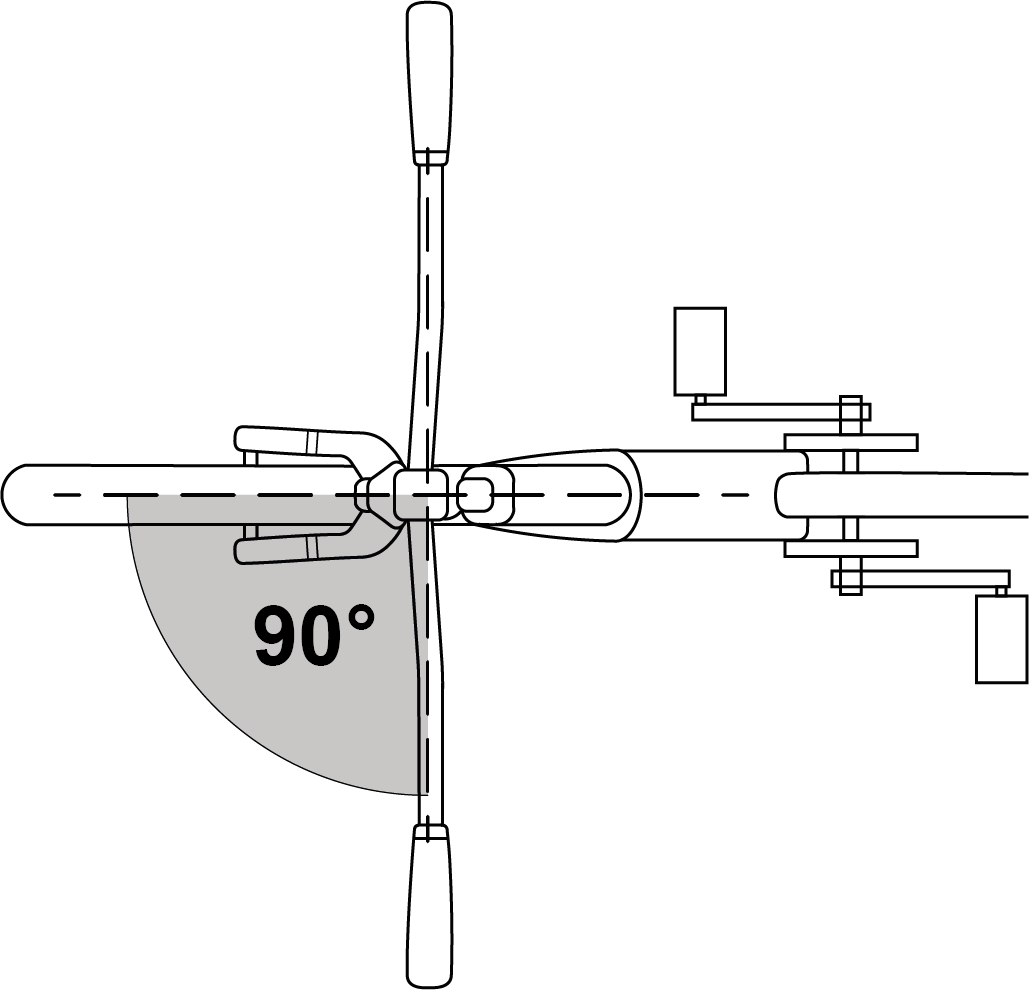
- Make sure that the handlebars are at a 90° angle to the front wheel.
- Check that the handlebars are firmly seated so that they do not twist during the ride and cause you to fall.
- Make sure that no cables are pulled or can get caught when you are steering.
- Ensure that the handles are firmly seated and in good condition. If the grips are loose or have cuts, cracks or worn areas, replace the grips or have them replaced by your MERIDA dealer.
- Make sure that the handlebar ends and any attachments are sealed with plugs. If the handlebar end plugs are damaged, replace them.
- For handlebars with attachments at the end of the handlebars, make sure that they are clamped in accordance with the manufacturer’s specifications for handlebars and attachments.
- Also make sure that handlebars, attachments, grips, brake levers and gear shifter are correctly attached and that safe handling of the bicycle, including unhindered steering, braking and gear shifting, is ensured.
Checking wheels
Spokes and rims
- Check the spokes and rims for damage.
Rotatability and tight fit in the frame
- Turn the front wheel - it should turn without lateral deflection in the fork and without touching any components.
- Turn the rear wheel - it should turn without lateral deflection in the fork and without touching any components.
- Check that the axles are fully seated in the dropouts.
- Lift your bike and hit the top of the tyre with your fist. The wheel must not fall out, be loose or move sideways.
Quick release
- If your bike is secured with a quick release, make sure that the lever is correctly positioned and flipped.
- Make sure that the quick release does not touch the following parts: fork, attachments, spokes or brake systems.
Tyre pressure
- Use a tyre pump with a pressure gauge to check whether the tyres are inflated to the recommended pressure.
- Always inflate the tyres as indicated on the tyre sidewalls or rims.
| Notice | |
|---|---|
Tyre wear
- Check the tyre wear on your bike.
- Replace the tyres if necessary.
Tyres with worn tread or brittle sidewalls pose a high risk of accidents and falls. The inner structure of the tyre can be damaged if dirt or moisture gets inside.
Valves
- Check that the valves are straight; damage to the tyres can cause the tube to burst suddenly.
Checking the saddle and seatpost
- Check that the saddle is correctly aligned and in line with the top tube.
- Check that the saddle rails or clamp are firmly seated to prevent the saddle from twisting, tilting or shifting during the ride.
Observe error messages on the e-system
Note the error messages or codes shown on your display. Correct this before you set off Troubleshooting.
After a fall or impact
| Warning | |
|---|---|
Inspect the frame and components for damage and do not continue your journey if you notice any damage!
The following components and functions must be checked:
Checking the steering stop
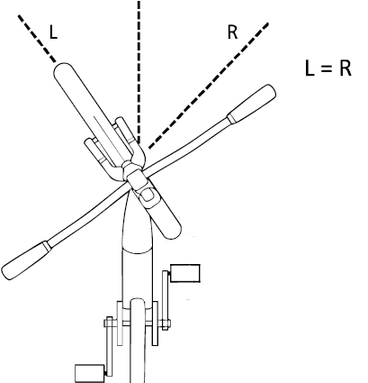
The integrated steering stop can twist in the event of a fall. Therefore, after a fall, it must be ensured that the steering stop is still centred by checking when stationary whether the handlebars can be turned to the left and right to the same extent.
Frame and suspension fork
- Check whether the frame or suspension fork is broken or bent.
- Check the carbon frame for cracks or soft spots in the carbon if your bike has a carbon frame.
| Notice | |
|---|---|
Gears and wheels
- Check the shifting system by shifting through all gears and making sure they run smoothly without any delays or noises.
- Check the wheels by spinning them and looking for lateral runout, dragging brakes and loose spokes or axle play.
If you find any damage to these parts, do not continue your ride!
Even if no damage can be detected, pay very close attention to any unusual noises from your bike as you continue your ride. These could indicate damage or other problems. Do not ride any further if you notice any unusual noises.
If you have any doubts about the condition of the material after a fall or accident, please always contact your MERIDA dealer. Some consequences of a fall or accident can only be recognised if the bike is completely dismantled and examined for cracks or other signs of damage.
Troubleshooting and repairs
In the event of error messages on the display unit, the Bosch user manual should be consulted for troubleshooting.
Then follow the steps in the Bosch user manual or contact your MERIDA dealer.
Fitting / dismantling a wheel
Your bike is equipped with thru axles. These give the suspension forks and the rear triangle the necessary stiffness.
Removable axle lever
Our MERIDA TR rear axle lever can be used to tighten the rear axle. When it is removed, it also serves as a 6 mm and 4 mm Allen key, which can be used to tighten many other screws on the bike.
To use the removable axle lever, pull out the lever on the non-drive side of the bike. To reinsert it, simply push it back into the centre of the thru axle.
A 6 mm Allen key is required to loosen the MERIDA thru axles on the rear wheel and fork. To do this, use the removable axle lever on your bike.
Handling the hex socket thru axle
Opening
- Loosen the thru axle by turning the axle lever (6 mm) anti-clockwise.
- Then pull out the thru axle.
Closing
- Push the axle through the frame and hub with the thread first.
- Tighten the thru axle clockwise using the axle lever (6 mm).
Fitting the rear wheel thru axle
The following section explains how to fit the rear wheel.
- Apply grease to the thread of the thru axle.
- Insert the rear wheel so that the opening for the thru axle of the hub and dropout are aligned.
- Push the thru axle from the non-drive side through the dropout and through the hub. The thru axle must touch the thread of the opposite dropout.
- Tighten the thru axle hand-tight by turning the axle lever clockwise.
- Remove the axle cover Removable axle lever
- Tighten the thru axle to 9 - 13.5 Nm using a torque spanner and a 6 mm hex bit.
Fitting the front wheel thru axle
The following user manual from the respective suspension fork manufacturer must be observed when fitting the thru axle to the front wheel:
- Rock Shox: (www.sram.com)
- Fox and Marzocchi: (tech.ridefox.com)
- SR Suntour: (www.srsuntour.com)
Removing the front wheel thru axle
To remove the thru axle from the front wheel, please refer to the following user manual from the respective suspension fork manufacturer:
- Rock Shox: (www.sram.com)
- Fox and Marzocchi: (tech.ridefox.com)
- SR Suntour: (www.srsuntour.com)
Removing the rear wheel thru axle
The following section explains how to remove the thru axle from the rear wheel.
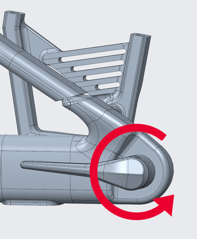
- Turn the axle lever anti-clockwise to release the thru axle.Figure 16. Turning the axle lever
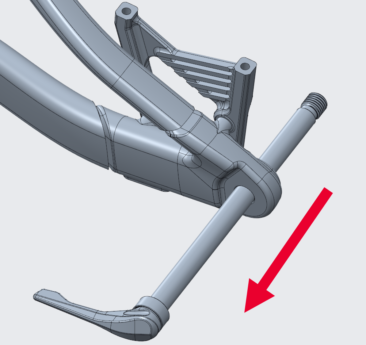
- Remove the thru axle in the direction of the non-drive side.Figure 17. Removing the thru axle
- Remove the rear wheel.
Maintenance and care
| CAUTION | |
|---|---|
Cleaning the bike
| CAUTION | |
|---|---|
Required utensils
- Water hose
- Bucket
- Mild soap / commercially available neutral detergent
- Soft brush
- Soft microfibre cloth
Procedure
- Wet your bike with a water hose and then clean it from top to bottom with a soft brush and, if necessary, with soapy water.
- Rinse the bike and wipe it dry with a microfibre cloth.
Lubricating the chain
| Warning | |
|---|---|
Proper lubrication ensures that the chain runs smoothly and quietly and extends its service life.
Depending on the degree of soiling, the chain must be cleaned at regular intervals to remove dirt and oil deposits. Special chain degreasers are not required.
Required utensils
- Suitable lubricant for bicycle chains
- Rags
Procedure
- Make sure that the electrical system is switched off.
- Raise the rear wheel slightly or hang the bike on an assembly stand.
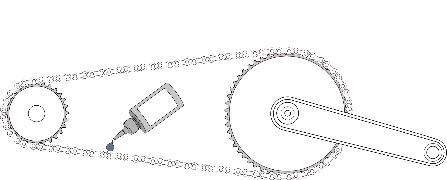
- Apply lubricant to the lower half of the chain on the chain links that are as bare as possible. This prevents the lubricant from dripping onto the chainstay or the wheel.
- Turn the pedals forwards and apply the chain oil drop by drop to the inside of the chain.
- Turn the chain through several revolutions.
- Leave the bike for a few minutes to allow the lubricant to penetrate the chain.
- Wipe off any excess lubricant with a cloth so that it does not become sharp or attract dirt unnecessarily during the next ride.
Maintenance schedule
Maintenance includes a complete check of all components.
The new bike should always be checked after the first ride.
After
- 100 km to 300 km of trips or
- 5 hours’ to 10 hours’ riding time or
- after four to six weeks, but
- after three months at the latest,
you should take your bike to your MERIDA dealer for an initial inspection.
The times given are intended as a guide, with an annual mileage of between 1,000 km and 2,000 km or between 50 hours and 100 hours of riding. The case that occurs first is decisive.
If you regularly ride on poor roads, the maintenance intervals will be shortened in line with the rougher use.
| Component group | Maintenance task | Interval |
| Frame | - Visual inspection for cracks & damage | Before every ride |
| - Check all screws for tightness | Monthly | |
| Headset bearings | - Check for ease of movement & play | Every six months |
| - Clean & grease bearings | Every six months | |
| - Replace worn bearings | As required | |
| Rear end | - Visual inspection for play & wear | Every six months |
| - Clean & grease bearings carefully | Every six months | |
| - Replace worn bearings | As required | |
| Suspension (fork & damper) | - Clean & lubricate seals | Every six months |
| - Check air pressure & damping settings | Monthly | |
| - Fork & damper oil service (depending on manufacturer) | Every six months | |
| Wheels & tyres | - Check tyre pressure & adjust if necessary | Before every ride |
| - Check tyres for cuts & tread wear | Monthly | |
| - Check spoke tension & concentricity of the wheels | Every six months | |
| Thru axles | - Check thru axles for tight fit | Monthly |
| - Clean & lightly grease threads | Every six months | |
| Drivetrain (chain, cassette, chainring, gears) | - Clean & lubricate chain | Before each ride/as required |
| - Adjust the gearstick | Every six months | |
| - Check chain for wear & replace if necessary | Every six months | |
| Bottom bracket | - Check for play & creaking noises | Every six months |
| - Removal, cleaning & greasing (for bolted bearings) | Annually | |
| - For press-fit bearings: Replacement in case of wear | As required | |
| Brakes | - Check brake pads & brake discs for wear | Monthly |
| - Change brake fluid | Annually | |
| Lighting | - Function test (front & rear light) | Monthly |
You can also carry out the maintenance work yourself if you have manual skills, some experience and suitable tools, e.g. a torque spanner. If defects are identified during the inspection, take action immediately.
Your MERIDA dealer will provide you with expert support on all maintenance issues.
Spare parts
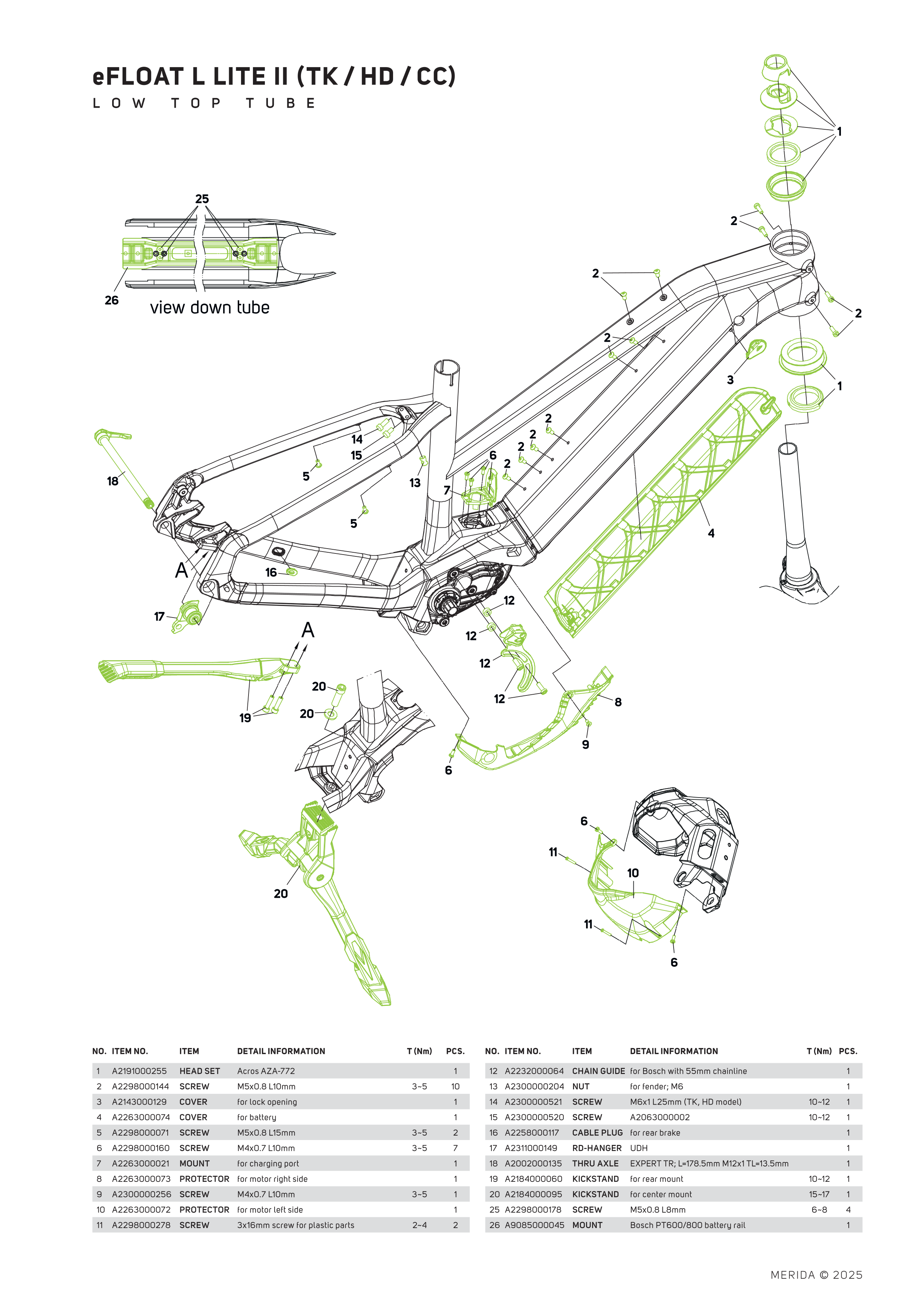
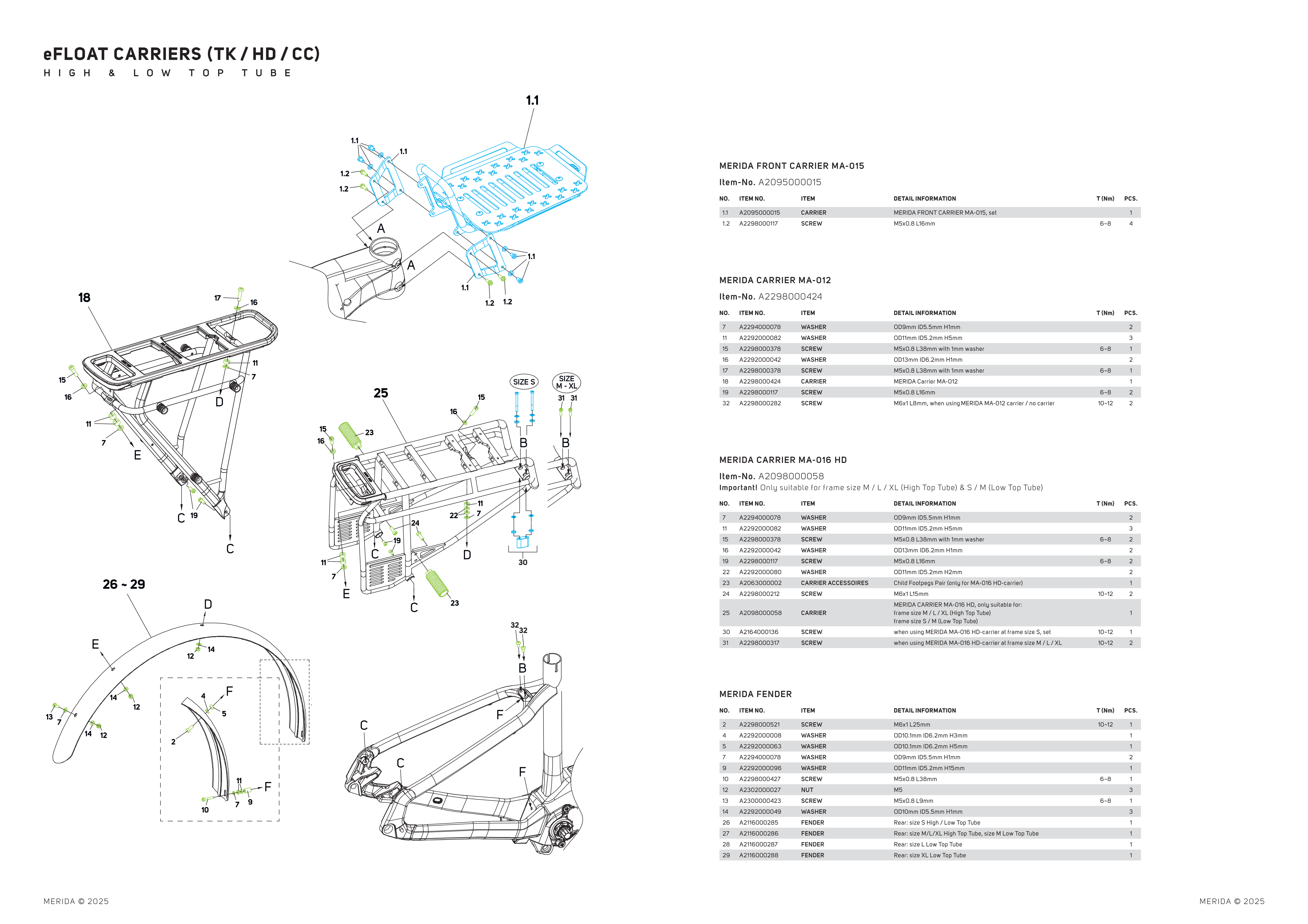
Spare parts can be ordered from your MERIDA dealer. The required MERIDA part numbers can be found in the exploded views.
Accessories
Carrier
| Warning | |
|---|---|
| Warning | |
|---|---|
| Luggage carrier interface | MID HD |
| Luggage carrier ex works | HD carrier |
| Maximum load | 40 kg |
| HD luggage carrier ex works | yes |
| Front luggage carrier: | |
| Front luggage carrier ex works | yes |
| Maximum load | 10 kg |
Front luggage carrier
The front luggage carrier is already factory-installed on your eFLOAT HD.
The maximum load for the front luggage carrier is 10 kg. The load must be secured with appropriate tensioning straps.
Check the free movement of the steering lock before every ride!
| Warning | |
|---|---|
| Warning | |
|---|---|
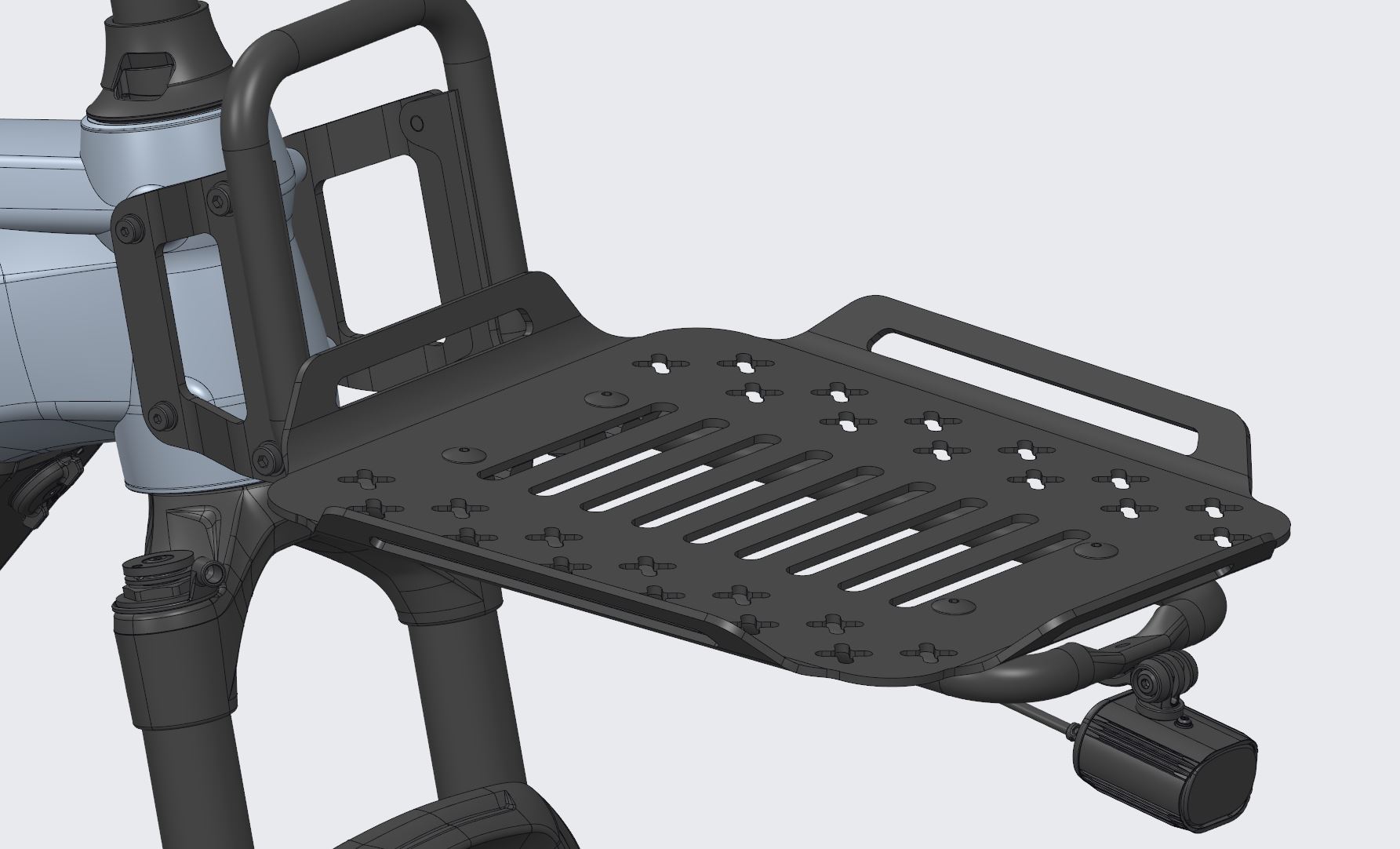
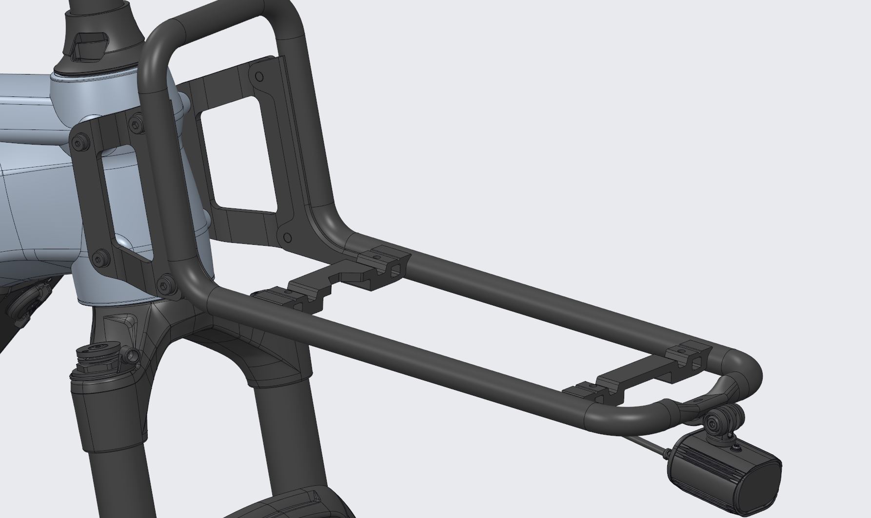
If the MIK holder is to be used instead of a loading area, the loading area can be removed by loosening the four screws. For example, a 40 x 30 x 12 cm bike box can be fitted on this MIK interface.
Child seat
The luggage carrier of the eFLOAT CITY, eFLOAT TK, eFLOAT CC and eFLOAT HD have an MIK HD interface. A child seat which is intended for MIK HD interfaces can be fitted on this interface.
With an eFLOAT HD, the child seat is fitted on the rear luggage carrier on the front of the two MIK HD holders.
| Warning | |
|---|---|
Tube Base Mount
Your aluminium frame has the tube base plate on top of the down tube.
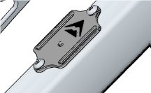
Product code A2161000227
For all tube attachments, we recommend wrapping the tape as shown:
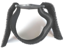
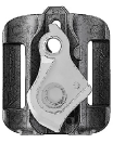
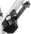
You can also attach the MERIDA TRAIL MOUNT, which can hold a spare UDH hanger, two 16g CO2 cartridges or a pump and a tube.
V-Mount with integrated multi-tool
Your bike contains a toolbox and a multi-tool under the saddle. The V-MOUNT allows the toolbox and multi-tool to be fitted under the saddle.
MERIDA Multi-tool 12-in-1
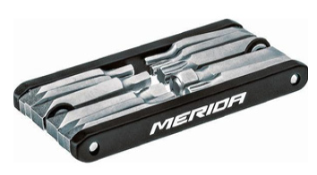
Multi-tool V-Mount box for installation under the saddle

The multi-tool contains the following tools:
- Allen keys: 2, 2.5, 3, 4, 5, 6, 8 mm
- Screwdriver: +/-
- Torx: T10, T25, T30
To use the multi-tool, open the flap of the toolbox and pull it out. To stow it away, simply push it back into the toolbox and close the flap.
To remove the whole box from the saddle, take the tool out of the box and detach the flap from the box by pulling the box out. Unscrew the box from the V-MOUNT using a 3 mm Allen key.
Range Extender
The BOSCH PowerMore 250 Range Extender can be retrofitted to your bike to increase the capacity of the rechargeable battery.
The matching cable is the 100 mm Bosch PowerMore cable with outlet from the battery holder.
The BOSCH PowerMore battery holder and the Range Extender cable are required for installation.
Bottle holder
| Frame | Diamond frame | Low frame | ||
| Bottle position | on the down tube | under the top tube | on the down tube | under the top tube |
| Bottle size | 0.75 litre | 0.5 litre | 0.75 litre | |
| FIDLOCK bottle holder integrated | no | |||
Side stand
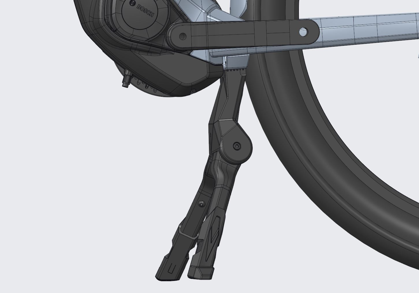
A side stand can be retrofitted with a holder for the side stand on the chain stay. The hole spacing is: 17 mm.
Matching rear stands: Product code A2184000084.
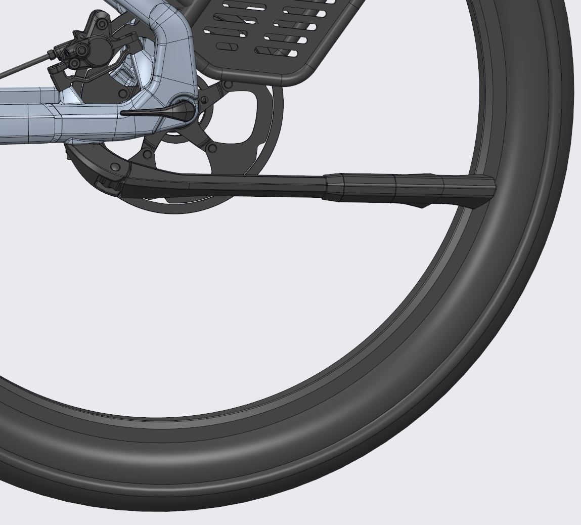
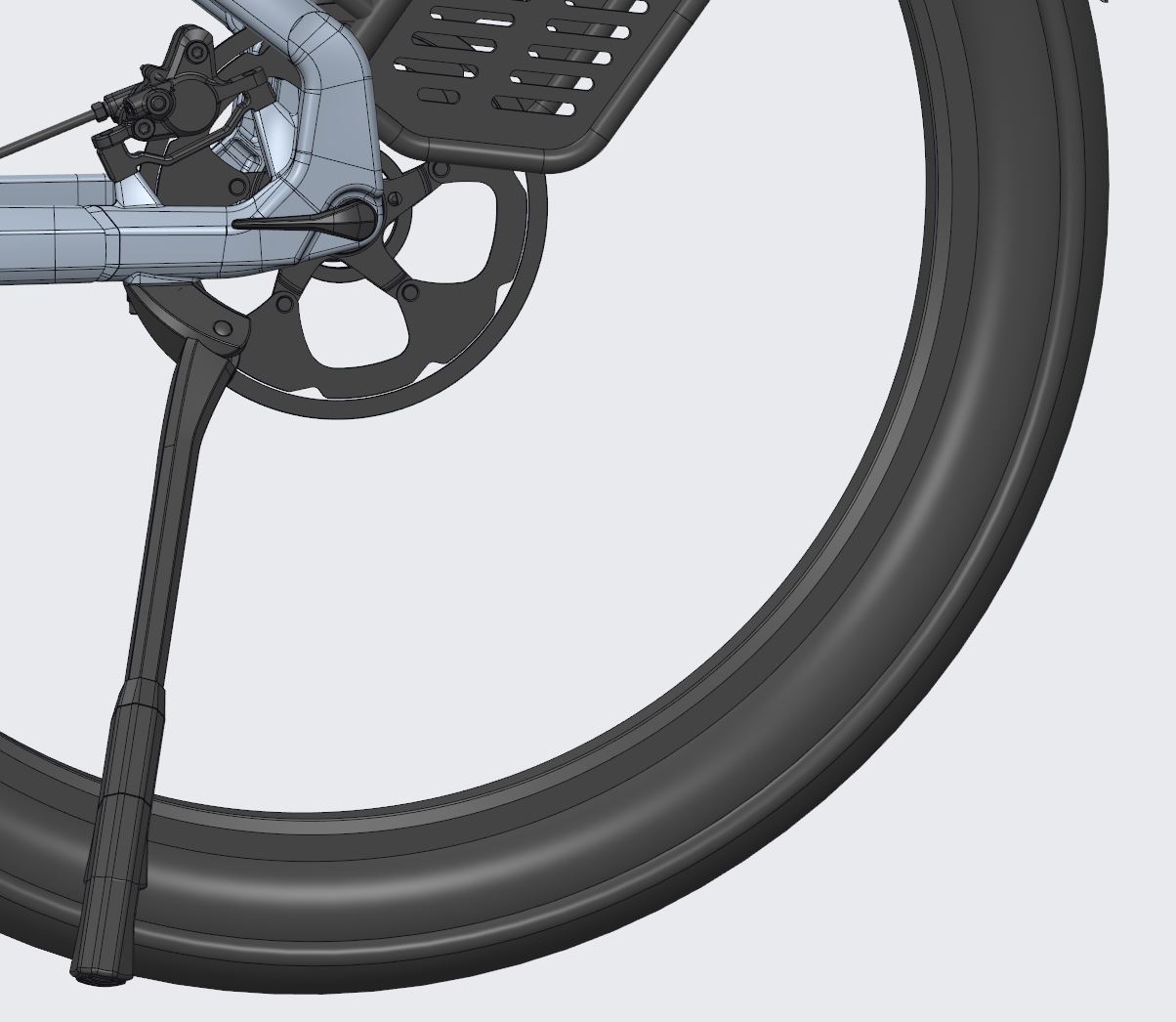
The eFLOAT CC, TK and HD models also have a double stand with the product code A2184000095.
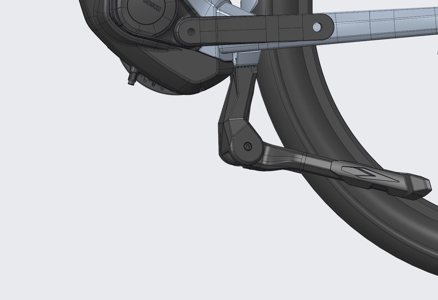
Frame lock
Before riding, make sure that the frame lock is open and that the key has been removed from the frame lock.
Technical Specifications
Maximum fork and spacer length
The maximum fork length, measured from the axle to the fork crown, is 545 mm. This corresponds to the dimensions of conventional suspension forks with 120 mm travel.
A maximum of 30 mm head tube spacers may be used.
Technical data of the frame
| eFLOAT HD L | eFLOAT HD | |
| Max. wheel size | 29 x 2.4" (w/o mudguard), 29 x 2.4" (with mudguard) | 29 x 2.4" (w/o mudguard), 29 x 2.4" (with mudguard) |
| Max. chainring size | ||
| Max. chainring size - Shimano Di2 | ||
| Max. chainring size - Shimano mechanical | ||
| Max. chainring size - SRAM eTAP AXS | ||
| Chainline | 53 mm | 53 mm |
| Max. small sprocket | ||
| Max. fork length | 545 mm | 545 mm |
| Headset upper | ZS56 | ZS56 |
| Headset lower rotation | 120° | 120° |
| Headset lower | ZS66 | ZS66 |
| Internal cable routing through Wireport | Yes | Yes |
| Internal cable routing shifting | Yes | Yes |
| Internal cable routing brake | Yes | Yes |
| Internal shock remote | ||
| Internal cable routing seatpost remote | Yes | Yes |
| External shifting | ||
| External brake | ||
| Di2 shifting ready | ||
| Di2 shifting only | ||
| Internal front light | Yes | Yes |
| Internal rear light | Yes | Yes |
| Brake type rear | Disc brake on chainstay | Disc brake on chainstay |
| Brake mount and standard rear | Post mount 180 mm rear brake | Post mount 180 mm rear brake |
| Max. rear brake rotor size | 203 mm | 203 mm |
| Brake type front | Depends on the fork specification | Depends on the fork specification |
| Brake mounting and standard front | Depends on the fork specification | Depends on the fork specification |
| Max. front brake rotor size | Depends on the fork specification | Depends on the fork specification |
| Bottom bracket standard | ||
| Seatpost diameter | 34.9 mm | 34.9 mm |
| Rear axle standard | Thru axle 12 x 148 mm | Thru axle 12 x 148 mm |
| Rear axle dimensions | 178.5 mm, M12xP1.0, 13.5 mm thread length, axle height 8.5 mm | 178.5 mm, M12xP1.0, 13.5 mm thread length, axle height 8.5 mm |
| Front axle standard | - | - |
| Front derailleur standard | ||
| Front derailleur cable pull | ||
| ISCG05 mount via adapter | ||
| Bottle cage mount (position/bottle size) | Downtube: range extender or 0.75l; TT: 0.75l | Downtube: range extender or 0.75l; TT: size S 0.5l, all others 0.75l |
| Bottle cage mount with adapter (position/bottle size) | ||
| Tool mount 39 mm (position) | ||
| Kickstand mount | Atran Velo Merida Custom 17mm | Atran Velo Merida Custom 17mm |
| Carrier mount frame | MA012 and HD carrier | MA012 and HD carrier |
| Mudguard mount frame | Yes | Yes |
| Mudguard mount fork | ||
| Frame lock | Yes | Yes |
| Carrier mount fork | ||
| Front light mount on crown | ||
| Fork bottle cage mount 64mm | ||
| Satellite interface | ||
| Battery interface | Bosch BES3 600Wh/800Wh | Bosch BES3 600Wh/800Wh |
| Range extender interface | On downtube | On downtube |
| Charging port interface | Bosch | Bosch |
| Motor interface | Bosch unified frame interface V2 | Bosch unified frame interface V2 |
| Speed sensor mount | Internal (rim) | Internal (rim) |
| Frame weight (size M, +/- 3%) | 4012 g | 4051 g |
| Fork weight (+/- 3%) | ||
| RD hanger | SRAM UDH | SRAM UDH |
Exploded view
The exploded view can be downloaded as a PDF from the following link:
Exploded view low top tube frame
Exploded view high top tube frame
Exploded view eFLOAT luggage carrier
Recycling and disposal
Do not dispose of your bike and its components in the household waste!
 | The product is labelled in accordance with European Directive 2012/19/EU of the European Parliament and of the Council on Waste Electrical and Electronic Equipment. The so-called WEEE Directive provides the framework for the EU-wide return and recycling of old equipment. This Directive lays down measures to protect the environment and human health in order to prevent or reduce the harmful effects of waste electrical and electronic equipment. The crossed-out wheelie bin symbol on the electrical and electronic parts, on the packaging or on the enclosed documents means that the product or parts must not be disposed of in the household waste and that a fine may be imposed in the event of non-compliance. Always contact the manufacturer or specialist retailer for further information on the collection and return system for used electrical and electronic equipment before you plan to dispose of it. In accordance with European Directive 2006/66/EC - Battery Disposal Act - defective and used batteries and rechargeable batteries must be collected separately and recycled in an environmentally friendly manner. It is the responsibility of the operator to dispose of and recycle the used product properly. Disposing of old equipment in accordance with the regulations protects the environment and the health of your fellow human beings from possible negative consequences. Material recycling helps to reduce the consumption of raw materials. |
If you need to dispose of your bike or parts of it, please always contact your MERIDA dealer. Disposal of the battery or rechargeable battery is required in accordance with the Battery Disposal Act. Your MERIDA dealer is obliged to take back your old rechargeable battery and dispose of it properly.